Breaker Wiring Diagram - Pin On Projects To Try : The wiring into a breaker must correspond to its amperage.. Wiring a four poles rcbo or gfci circuit breaker (three phase rccb wiring) the three phase wiring for gfci or rcd (rccb) or rcbo wiring diagram shows the three lines (l1, l2 and l3) and neutral has been connected as input to the rccb from main board followed by mcb i.e. What is the purpose of a shunt trip circuit breaker the main purpose of a shunt trip breaker is that we can easily switch off main circuit breaker form our nearest place in short time and can safe us from electrical accidents. It shows the parts of the circuit as simplified forms, as well as the power and signal links in between the gadgets. Connect each of the hot wires on the cable to one of the lugs on the breaker and snap the breaker into an available slot on the panel. Standing to the side of the panel, restore power to the panel by setting the service disconnect or main to on and then set the new circuit breaker to on.
Wiring installation of single phase 120v & 240v circuits & breakers in main service panel. This circuit breaker wiring diagram illustrates installing a 20 amp circuit breaker for a 240 volt circuit. A neutral wire is not used in this circuit. How to wire an electrical circuit breaker panel. What is the purpose of a shunt trip circuit breaker the main purpose of a shunt trip breaker is that we can easily switch off main circuit breaker form our nearest place in short time and can safe us from electrical accidents.
Circuit Breaker Wiring Diagrams Do It Yourself Help Com Electrical Wiring Home Electrical Wiring Basic Electrical Wiring from i.pinimg.com Connect each of the hot wires on the cable to one of the lugs on the breaker and snap the breaker into an available slot on the panel. A breaker panel box, 15amp, 20amp, 30amp, 50amp, and gfci breakers. Sf6 circuit breaker what are they types and operation electrical4u. A wiring diagram is a simplified traditional photographic depiction of an electric circuit. Turn on the main breaker and test your new circuit breaker. The wiring into a breaker must correspond to its amperage. Circuit breaker control operation and captured trip coil scientific diagram. A wiring diagram is a simplified conventional photographic representation of an electrical circuit.
Connect each of the hot wires on the cable to one of the lugs on the breaker and snap the breaker into an available slot on the panel.
Without a circuit breaker, you could find yourself dealing with household fires on a regular basis. On afci or gfci breakers, this circuit wire will be attached to the terminal marked load power or black. finally, for afci or gfci breakers, attach the breaker's coiled white pigtail wire to the neutral bus bar in the panel. Wiring installation of single phase 120v & 240v circuits & breakers in main service panel. Here is the rcd wiring diagram in which i install the main distribution board. Here is complete explanation of shunt trip circuit breaker wiring diagram which help you understanding completely. A breaker panel box, 15amp, 20amp, 30amp, 50amp, and gfci breakers. Circuit breaker control operation and captured trip coil scientific diagram. Circuit breaker wiring diagrams do it yourself help rh eaton circuit breaker with test on awesome hot tub panel rh east pre 50 gfci gfci breaker wiring diagram simple circuit beautiful diagrams spas pools spa motor square d 50 gfci breaker wiring electrical work diagram on leviton nice gfci internal wiring diagram new 50. Mastering gis control circuits ac dc auxiliary and circuit breaker closing eep. Basics 14 aov schematic (with block included) basics 15 wiring (or connection. Basics 13 valve limit switch legend : Turn on the main breaker and test your new circuit breaker. Connect each of the hot wires on the cable to one of the lugs on the breaker and snap the breaker into an available slot on the panel.
Basics 8 aov elementary & block diagram : Without a circuit breaker, you could find yourself dealing with household fires on a regular basis. Tutorial for wiring a shunt trip qo™ (and qob) circuit breaker. Here is complete explanation of shunt trip circuit breaker wiring diagram which help you understanding completely. It shows the parts of the circuit as simplified forms, as well as the power and signal links in between the gadgets.
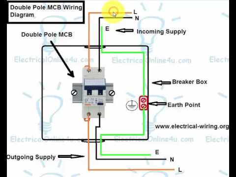
How To Wire Double Pole Breaker Mcb In English Youtube from i.ytimg.com Variety of 3 pole circuit breaker wiring diagram. Shunt trips (accessories) in qo™ breakers are factory installed only and can not be added to. It shows the parts of the circuit as simplified forms, as well as the power and signal links in between the gadgets. Sf6 circuit breaker what are they types and operation electrical4u. Basics 13 valve limit switch legend : The wires usually are black or red, but one may be white if it is labeled as hot with a black or red stripe near each end. A breaker panel box, 15amp, 20amp, 30amp, 50amp, and gfci breakers. In this configuration, the black wire connects to the breaker, and the white and bare wires connect to the ground bus.
It shows the parts of the circuit as simplified forms, as well as the power and signal links in between the gadgets.
What is the purpose of a shunt trip circuit breaker the main purpose of a shunt trip breaker is that we can easily switch off main circuit breaker form our nearest place in short time and can safe us from electrical accidents. Collection of circuit breaker wiring diagram. With all circuit wires connected, the circuit breaker can be snapped into place into its panel slot. We will be using this simple diagram to discuss the components involved with the electrical operating sequence of a circuit breaker. Circuit breaker wiring diagrams do it yourself help rh eaton circuit breaker with test on awesome hot tub panel rh east pre 50 gfci gfci breaker wiring diagram simple circuit beautiful diagrams spas pools spa motor square d 50 gfci breaker wiring electrical work diagram on leviton nice gfci internal wiring diagram new 50. Circuit breaker wiring diagrams do it a box bo diagram diy 240 full with switch 30 amp dryer outlet switched light for your upgrade 100 fuse to 220 plug wire how house yourself electrical works electric breakers 101 an panel install gfci tos instructions hot tub 60 home system explained twist lock laser show systems support equipment single line. Wiring installation of single phase 120v & 240v circuits & breakers in main service panel. Basics 14 aov schematic (with block included) basics 15 wiring (or connection. Standing to the side of the panel, restore power to the panel by setting the service disconnect or main to on and then set the new circuit breaker to on. Mastering gis control circuits ac dc auxiliary and circuit breaker closing eep. The 12/2 gauge cable for this circuit includes 2 conductors and 1 ground. Switchboard, and provides indication to the system on the breaker position. In this video you will learn about how to wire double pole mcb (miniature circuit breaker) with wiring connection diagram in english language.for video visit.
With all circuit wires connected, the circuit breaker can be snapped into place into its panel slot. Basics 10 480 v pump schematic : Wiring a four poles rcbo or gfci circuit breaker (three phase rccb wiring) the three phase wiring for gfci or rcd (rccb) or rcbo wiring diagram shows the three lines (l1, l2 and l3) and neutral has been connected as input to the rccb from main board followed by mcb i.e. 5wire the new circuit breaker. L3 circuit breaker stop start m ot* t1 t2 t3 m m solid state overload relay 1ct m m motor 3ct to 120 v separate control * ot is a switch that opens when an overtemperature.
How To Wire A Double Pole Circuit Breaker Electricalonline4u from 1.bp.blogspot.com A breaker circuit is an electrical switch that cuts off electrical flow in the event of a possible short circuit or overload. Variety of 3 pole circuit breaker wiring diagram. Power circuit breaker operation and control scheme peguru. Basics 8 aov elementary & block diagram : Check for correct operation of the new circuit (light, outlet, etc.) with a test light or meter. L3 circuit breaker stop start m ot* t1 t2 t3 m m solid state overload relay 1ct m m motor 3ct to 120 v separate control * ot is a switch that opens when an overtemperature. In this video you will learn about how to wire double pole mcb (miniature circuit breaker) with wiring connection diagram in english language.for video visit. It reveals the parts of the circuit as simplified shapes, as well as the power and signal links in between the devices.
This circuit breaker wiring diagram illustrates installing a 20 amp circuit breaker for a 240 volt circuit.
The wires usually are black or red, but one may be white if it is labeled as hot with a black or red stripe near each end. Lw8 40 5 sf6 circuit breaker. The 12/2 gauge cable for this circuit includes 2 conductors and 1 ground. A wiring diagram is a simplified conventional photographic representation of an electrical circuit. Wiring diagram since wiring connections and terminal markings are shown, this type of diagram is helpful when wiring the. Wiring a four poles rcbo or gfci circuit breaker (three phase rccb wiring) the three phase wiring for gfci or rcd (rccb) or rcbo wiring diagram shows the three lines (l1, l2 and l3) and neutral has been connected as input to the rccb from main board followed by mcb i.e. It reveals the parts of the circuit as simplified shapes, as well as the power and signal links in between the devices. A breaker panel box, 15amp, 20amp, 30amp, 50amp, and gfci breakers. Collection of shunt trip breaker wiring diagram. In this video you will learn about how to wire double pole mcb (miniature circuit breaker) with wiring connection diagram in english language.for video visit. Switchboard, and provides indication to the system on the breaker position. Shunt trips (accessories) in qo™ breakers are factory installed only and can not be added to. Sf6 circuit breaker what are they types and operation electrical4u.