Home
› 4 Wire Maf Sensor Wiring Diagram - Gm Maf Sensor Wiring Diagram - Wiring Diagram Schemas : Truck would start and run for a couple seconds and die.
4 Wire Maf Sensor Wiring Diagram - Gm Maf Sensor Wiring Diagram - Wiring Diagram Schemas : Truck would start and run for a couple seconds and die.
4 Wire Maf Sensor Wiring Diagram - Gm Maf Sensor Wiring Diagram - Wiring Diagram Schemas : Truck would start and run for a couple seconds and die.. What output do i need? Using an applicable wiring diagram. Electrical wiring representations will certainly also consist of panel timetables for breaker panelboards, and riser diagrams for unique services such as smoke alarm or closed circuit television or other special. F150 f250 f350 mustang crown victoria. It emits an ultrasound at 40 000 hz (40khz) which travels through the air and if there is an object or obstacle on its path it will bounce if you want to display it on lcd, you can follow the second wiring diagram and upload the code below.
Car side 3pins (other 2 are empty), show 5v, 0v, 12v against ground at 0, open, 0. Maf sensor & wiring diagrams amazon printed books www.createspace.com/3623928 amazon kindle edition. If the maf sensor has 6 wires then this is a dead giveaway that it has the air temp sensor integrated inside. How can i test the maf sensor to tell if it's working or not aside from just putting in a new one and comparing? Truck would start and run for a couple seconds and die.
| Repair Guides | Components & Systems | Manifold Absolute ... from repairguide.autozone.com Or is it just a straight shot from one to the other? No, only 4 wires go to the sensor. Blue oval chips how to wire your maf upgrade correctly. It runs fine and code is gone but the acceration lag is still there. Need to trace pig tail at sensor back to ecu. I have connected the +12v, +5v, ground, and signal wires. Can someone post the wiring diagram for the maf sensor? It emits an ultrasound at 40 000 hz (40khz) which travels through the air and if there is an object or obstacle on its path it will bounce if you want to display it on lcd, you can follow the second wiring diagram and upload the code below.
Using an applicable wiring diagram.
Maf sensor wiring diagram excellent wiring diagram products. Otherwise you'd need a wiring diagram and a volt meter, find the signal wire, and see if your voltage changes correctly with increased airflow. Here well walk you through the whole process of testing and troubleshooting the ford. In the photo above you can see a 4 wire maf sensor. Fighting supply voltage code, already swapped sensor. Ok so i have a 2002 1.8t awp, which one's the ground wire and which ones the maf 5v signal. Maf, iat/map sensor, dbw pedal, ecu, ecu. Truck would start and run for a couple seconds and die. Read cabling diagrams from unfavorable to positive in addition to redraw the signal like a straight collection. These can be mounted further away from the exhaust port as they are self heating. Maf sensor wiring diagram top electrical wiring diagram. Can someone post the wiring diagram for the maf sensor? Check wiring for open circuits between the ecmtest box and the 3 pin maf sensor harness connector.
Ford maf sensor testing, 12v power you do not need a scan tool to test the mass air flow sensor on your ford. 5v maf signal output i think that's what you're asking for. Read cabling diagrams from unfavorable to positive in addition to redraw the signal like a straight collection. Checking wiring for mass air flow (maf) sensor. Refer to the diagrams on the following pages.
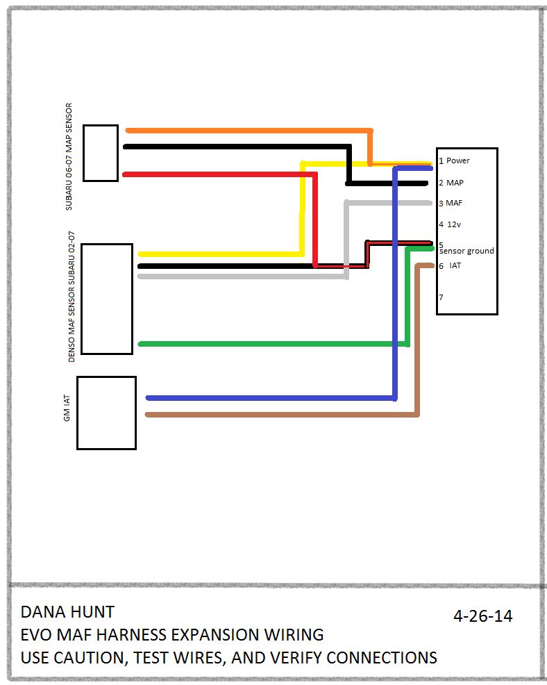
4 Wire Maf Sensor Wiring Diagram - Wiring Diagram Schemas from www.evolutionm.net I have connected the +12v, +5v, ground, and signal wires. Check wiring for open circuits between the ecmtest box and the 3 pin maf sensor harness connector. Refer to the diagrams on the following pages. It runs fine and code is gone but the acceration lag is still there. Otherwise you'd need a wiring diagram and a volt meter, find the signal wire, and see if your voltage changes correctly with increased airflow. Maf sensor wiring diagram top electrical wiring diagram. All circuits are usually the same ~ voltage, ground, individual component, and switches. Checking wiring for mass air flow (maf) sensor.
I have connected the +12v, +5v, ground, and signal wires.
I'm also replacing my intake air temp sensor with a delco sensor and connect the wires coming from the delco iat sensor to the wiring of the maf sensor since it has a built in iat sensor. Box on the right column to check for specific application info. Does anyone have a diagram for this. Or is it just a straight shot from one to the other? 3 wire to 5 wire maf wiring diagram ls1tech camaro and. Need to trace pig tail at sensor back to ecu. Does the wiring from the ecu to the maf go through any kind of relay or anything? It runs fine and code is gone but the acceration lag is still there. Blue oval chips how to wire your maf upgrade correctly. Read cabling diagrams from unfavorable to positive in addition to redraw the signal like a straight collection. Ford maf sensor testing, 12v power you do not need a scan tool to test the mass air flow sensor on your ford. Here well walk you through the whole process of testing and troubleshooting the ford. If the maf sensor has 6 wires then this is a dead giveaway that it has the air temp sensor integrated inside.
=> electrical wiring diagrams, troubleshooting & component locations. These can be mounted further away from the exhaust port as they are self heating. This is determined by the device you are connecting the sensor to. No, only 4 wires go to the sensor. How can i test the maf sensor to tell if it's working or not aside from just putting in a new one and comparing?
SOLVED: Automatic tranmission not working on overdrive ... from 4.bp.blogspot.com Inspect the following wiring harnesses for open or. Or is it just a straight shot from one to the other? Maf sensor wiring diagram top electrical wiring diagram. I put on a new oem maf sensor. How can i test the maf sensor to tell if it's working or not aside from just putting in a new one and comparing? Check wiring for open circuits between the ecmtest box and the 3 pin maf sensor harness connector. Ford maf sensor testing, 12v power you do not need a scan tool to test the mass air flow sensor on your ford. Proceed to clean it including wiring.
Disconnect the maf sensor connector.
Does anyone have a diagram for this. Maf, iat/map sensor, dbw pedal, ecu, ecu. Inspect the following wiring harnesses for open or. Maf sensor wiring diagram top electrical wiring diagram. These can be mounted further away from the exhaust port as they are self heating. Manifold absolute pressure (map) sensor. Otherwise you'd need a wiring diagram and a volt meter, find the signal wire, and see if your voltage changes correctly with increased airflow. Disconnect the maf sensor connector. Blue oval chips how to wire your maf upgrade correctly. Refer to the diagrams on the following pages. On my '05 awp, this is the wiring for my maf: => electrical wiring diagrams, troubleshooting & component locations. It runs fine and code is gone but the acceration lag is still there.