Home
› Hvac Control Wiring Diagram : Find Out Here Hvac Heat Pump Wiring Diagram Download - Contactor wiring for 3 phase motor with circuit breaker, overload relay diagram, normally open and a platform to learn electrical wiring, single phase, 3 phase wiring, controlling, hvac, electrical in this wiring diagram contactor, i have shown the thermal overload relay however soon i will make a.
Hvac Control Wiring Diagram : Find Out Here Hvac Heat Pump Wiring Diagram Download - Contactor wiring for 3 phase motor with circuit breaker, overload relay diagram, normally open and a platform to learn electrical wiring, single phase, 3 phase wiring, controlling, hvac, electrical in this wiring diagram contactor, i have shown the thermal overload relay however soon i will make a.
Hvac Control Wiring Diagram : Find Out Here Hvac Heat Pump Wiring Diagram Download - Contactor wiring for 3 phase motor with circuit breaker, overload relay diagram, normally open and a platform to learn electrical wiring, single phase, 3 phase wiring, controlling, hvac, electrical in this wiring diagram contactor, i have shown the thermal overload relay however soon i will make a.. The electrical line wiring diagram is often called. You can draw a picture showing where the different colored wires will connect to your replacement capacitor. Schneider electric… st (structured text in c within a dedicated window) fbd (function block diagram) multitasking ability function blocks dedicated to hvac & r applications programming via. All documents are in pdf format and will require acrobat reader. Riser diagrams showing control network layout, communication protocol.
Free furnace, heat pump, air conditioner installation & service manuals, wiring diagrams, parts lists. An hvac system is designed to combust fuels or consume electrical energy to provide heating or cooling to a conditioned space. Salam kenal juga, anda bisa mengikuti diskusi tentang hvac&r disini: Click the icon or the document title to download the pdf. A space is defined as individually controlled only when a dedicated terminal unit (example:
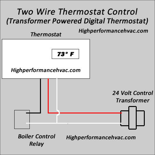
Thermostat Wiring Diagrams Wire Installation Simple Guide from highperformancehvac.com Schematic diagrams for all field sensors and controllers. Lower power wireless connectivity for remote valve controls in industrial spaces. Provide floor plans of all sensor locations and control hardware. Wiring diagrams wiring diagrams are used to allow unskilled workers to complete wiring of equipment. In order for students to be successful in the installation and service: Name three types of automatic controls. December 16, 2010 at 2:13 am. The links below are to current bard product wiring diagrams.
Validity note this document is valid for somachine hvac 2.0.
When working with a thermostat the cover can be snapped off to expose the wiring. In the detailed design phase, the electrical designer must size and select the wires/cables, conduits, starters, disconnects and switchgear necessary for supplying power and control to hvac equipment. Contains all the essential wiring diagrams across our range of heating controls. Hvac unit 15 review questions and review test learn with flashcards, games and more — for free. Bacnet ms/tp bacnet ms/tp infinet or wireless infinet. Many people can read and understand schematics known as label or line diagrams. Wiring diagrams and layouts for each control panel. The fresh air ventilation control™ (favc) which is part of the field controls healthy home system™ product line interactively works with residential hvac system thermostat, in conjunction with the central fan air handler system to periodically introduce controlled amounts of fresh air into the. 3.4 heating and ventilation units (hvu) • publishing design information • including functional diagrams and layout plates • listing standards. Hvac & r machine control solutions. An hvac system is designed to combust fuels or consume electrical energy to provide heating or cooling to a conditioned space. Wiring diagrams help technicians to see how the controls are wired to the system. These diagrams depict some commonly used and frequently installed configurations but may not match your hvac system.
Our wiring diagrams section details a selection of key wiring diagrams focused around typical sundial s and y plans. Before doing any work on the thermostat and wiring take a picture off the wires and their connections, or write them down. The fresh air ventilation control™ (favc) which is part of the field controls healthy home system™ product line interactively works with residential hvac system thermostat, in conjunction with the central fan air handler system to periodically introduce controlled amounts of fresh air into the. This type of diagram is like taking a photograph of the parts and wires all connected up. These systems must be controlled and made safe.
Ddc Panel Wiring Diagram Pdf from i0.wp.com Hvac unit 15 review questions and review test. Click the icon or the document title to download the pdf. Free furnace, heat pump, air conditioner installation & service manuals, wiring diagrams, parts lists. Hvac program, the following provide the students with an illustration or. Wiring diagrams help technicians to see how the controls are wired to the system. How to diagnose and repair your air conditioner (a/c) capacitor. This video covers manual and automatic hvac systems found. Operating controls sense temperature and signal the system to operate or shut off and rest.
The electrical line wiring diagram is often called.
Click the icon or the document title to download the pdf. Marine accommodation air conditioner piping diagram. Before doing any work on the thermostat and wiring take a picture off the wires and their connections, or write them down. Temperature) with a target state. Usually a sensing device is used to compare the actual state (e.g. • determine the wired flush mount sensor placement using the following recommendations and diagram. Free furnace, heat pump, air conditioner installation & service manuals, wiring diagrams, parts lists. Salam kenal juga, anda bisa mengikuti diskusi tentang hvac&r disini: Bacnet ms/tp bacnet ms/tp infinet or wireless infinet. You can draw a picture showing where the different colored wires will connect to your replacement capacitor. Buderus produces heating boilers, hot water tanks, radiant heating equipment, hvac controls, solar heating equipment, and information about discontinued products. A space is defined as individually controlled only when a dedicated terminal unit (example: There are no standards for hvac control wiring.
In order for students to be successful in the installation and service: Salam kenal juga, anda bisa mengikuti diskusi tentang hvac&r disini: The function blocks described in this document the block diagram presents on the left hand side the inputs, the process variables, on the right hand side. When working with a thermostat the cover can be snapped off to expose the wiring. Many people can read and understand schematics known as label or line diagrams.
Programmable Thermostat Wiring Diagrams | HVAC Control from highperformancehvac.com Operating controls sense temperature and signal the system to operate or shut off and rest. 3.4 heating and ventilation units (hvu) • publishing design information • including functional diagrams and layout plates • listing standards. Bacnet ms/tp bacnet ms/tp infinet or wireless infinet. Many people can read and understand schematics known as label or line diagrams. Usually a sensing device is used to compare the actual state (e.g. In order for students to be successful in the installation and service: Precise motor control of system valve for efficient water pump motor and precise flow control. Contactor wiring for 3 phase motor with circuit breaker, overload relay diagram, normally open and a platform to learn electrical wiring, single phase, 3 phase wiring, controlling, hvac, electrical in this wiring diagram contactor, i have shown the thermal overload relay however soon i will make a.
Honeywell building controls commercial hvac solutions light commercial hvac control.
These diagrams show the actual location of. The links below are to current bard product wiring diagrams. In part 3 of the wiring diagram series, it's time to dive into 2 slightly more difficult diagrams. Contains all the essential wiring diagrams across our range of heating controls. Bacnet ms/tp bacnet ms/tp infinet or wireless infinet. Riser diagrams showing control network layout, communication protocol. Before doing any work on the thermostat and wiring take a picture off the wires and their connections, or write them down. There are no standards for hvac control wiring. These diagrams depict some commonly used and frequently installed configurations but may not match your hvac system. This video covers manual and automatic hvac systems found. When working with a thermostat the cover can be snapped off to expose the wiring. Schematic diagrams for all field sensors and controllers. • determine the wired flush mount sensor placement using the following recommendations and diagram.