2X1 Mux Logic Diagram : 2 X 1 Multiplexer Youtube : Hanya anggota dari blog ini yang dapat mengirim komentar.. Implementing a function of 3 variables with a 4x1 mux: Implementing 8x1 mux using 2x1 mux contribute: When sel is at logic 0 out=i0 and when select is at logic 1 out=i1. The block diagram of mux with n data sources of b bits wide and s bits wide select line is shown in below figure. Q3 (implement equation using half adder).
Implement a full adder with two 4 x 1 multiplexers. Tpzl output waveform 1 vo s1 at 2 x vcc (see note b). Basically to implement a full adder, two 4:1 mux is needed. • the multiplexers can have the outputs active high (like in previous figures), or active low. The logic circuit and symbol of 2x1 mux is shown in figure 2.
A Report On 2 To 1 Mux Using Tg from cdn.slidesharecdn.com Mux mux is a device which has 2n input lines. To implement the above for every gate, either we can derive the different gates using the logic (the truth table) or the procedure to. Following is the logic diagrams for 8x1 mux using two 4x1 mux. The general block level diagram of a multiplexer is shown below. Q3 (implement equation using half adder). But, to obtain the same for a 16:1 mux you'll need to make a lot of modifications. Basically to implement a full adder, two 4:1 mux is needed. First, we'll start by declaring the modules for each logic gate.
The implementation of not gate is done using n selection lines.
A transmission gate is an electronic element and good non mechanical relay. Mux mux is a device which has 2n input lines. It has 4 select lines and 16 inputs. How to construct or logic gate using nand logic gate ic. 3 665 просмотров 3,6 тыс. The various analyses are established more on compressors circuits particularly with multiplexer (mux) design. We can analyze it y = x'.1 + x.0 = x' it is not gate using 2:1 mux. Vhdl code of 8x1mux using two 4x1 mux : I tackled your question using logic friday 1: Tpzl output waveform 1 vo s1 at 2 x vcc (see note b). The remaining single variable of the function is used for the. Output follows one of the inputs depending upon the state of the select lines. But, to obtain the same for a 16:1 mux you'll need to make a lot of modifications.
Following is the logic diagrams for 8x1 mux using two 4x1 mux. We can analyze it y = x'.1 + x.0 = x' it is not gate using 2:1 mux. Basically to implement a full adder, two 4:1 mux is needed. Like if you draw the truth table and analyze (compare it with the above 8:1 mux design), you'll require two. Now from the above diagram the conclusion can be drawn after writing the truth table of logic as shown by mahesh we can write the sum function as sum = cin.not.
Multiplexers In Digital Logic Geeksforgeeks from media.geeksforgeeks.org Implementing a function of 3 variables with a 4x1 mux: A logic block is diagrammed as a box. Implement a full adder with two 4 x 1 multiplexers. 08.01.2019 · logic diagram for 81 mux you can observe that the input signals are d0 d1 d2 d3 d4 d5 d6 d7 s0 s1 s2 and the output signal is out. A multiplexer is also called a data selector. A 16x1 mux can be implemented from 15 2:1 muxes. Q3 (implement equation using half adder). Derive the truth table that defines the required relationship 2.
But, to obtain the same for a 16:1 mux you'll need to make a lot of modifications.
2:1 mux verilog in data flow model is given below. How to make 8x1 multiplexer using 2 4x1 multiplexer? The schematic diagram, boolean equation and the truth table of a 2:1 design using transmission gate logic. All the standard logic gates can be implemented with multiplexers. Implementing a function of 3 variables with a 4x1 mux: • the multiplexers can have the outputs active high (like in previous figures), or active low. Vhdl code of 8x1mux using two 4x1 mux : How to construct or logic gate using nand logic gate ic. The logic circuit and symbol of 2x1 mux is shown in figure 2. Like if you draw the truth table and analyze (compare it with the above 8:1 mux design), you'll require two. The remaining single variable of the function is used for the. Q3 (implement equation using half adder). A logic block is diagrammed as a box.
The implementation of not gate is done using n selection lines. Hanya anggota dari blog ini yang dapat mengirim komentar. All the standard logic gates can be implemented with multiplexers. 2:1 mux verilog in data flow model is given below. The truth table of 4x1 mux is :
Vlsi Universe 2x1 Mux Using Nand Gates from 4.bp.blogspot.com Tpzl output waveform 1 vo s1 at 2 x vcc (see note b). The logic circuit and symbol of 2x1 mux is shown in figure 2. Vhdl code of 8x1mux using two 4x1 mux : Implementing 8x1 mux using 2x1 mux contribute: The implementation of not gate is done using n selection lines. Now from the above diagram the conclusion can be drawn after writing the truth table of logic as shown by mahesh we can write the sum function as sum = cin.not. The symbol used in logic diagrams to identify a multiplexer is as follows 2:1 mux verilog in data flow model is given below.
3 665 просмотров 3,6 тыс.
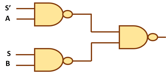
The various analyses are established more on compressors circuits particularly with multiplexer (mux) design. 4x1 multiplexer has four data inputs i3, i2, i1 & i0, two selection lines s1 & s0 and one output y. A multiplexer of 2 n inputs has n select lines, which are used to select which input line to send to the output. You need a combinational logic with 16 input pins, 4 select lines and one output. Nand gate using 2x1 mux. Q3 (implement equation using half adder). First, we'll start by declaring the modules for each logic gate. A transmission gate is an electronic element and good non mechanical relay. Implement a full adder with two 4 x 1 multiplexers. We can analyze it y = x'.1 + x.0 = x' it is not gate using 2:1 mux. A 16x1 mux can be implemented from 15 2:1 muxes. Basically to implement a full adder, two 4:1 mux is needed. Mux in front of alu.