Home
› Ladder Logic Diagram Symbols / Ladder Logic Basics Ladder Logic World / • continuous motor operation with a momentary start switch is possible if a.
Ladder Logic Diagram Symbols / Ladder Logic Basics Ladder Logic World / • continuous motor operation with a momentary start switch is possible if a.
Ladder Logic Diagram Symbols / Ladder Logic Basics Ladder Logic World / • continuous motor operation with a momentary start switch is possible if a.. The vertical lines on the left and right are called the power rails. Unlike the two symbols above, the output energize will be used to execute an action. Ladder logic is a graphical based industrial programming language used to program and configure programmable ladder logic programming is like virtual circuit building. Ladder diagrams differ from regular schematic diagrams of the sort common to electronics technicians primarily in the strict orientation of the wiring: —( )— a regular coil, energized whenever its rung is closed.
Draw ladder diagrams for simple logic operations. Early relay diagram symbols were literal. Ladder diagram systems are the best programming language to learn and the smart thing that the designers did was make it very similar to standard since we started this plc tutorial with how a plc works and what it is then continued to what ladder logic symbols are then talked about timers and. It has a short abbreviation as 'ld' and also known as 'ladder logic'. The ladder diagram is the universal programming language of plc.
Ladder Logic Programming Examples Ladder Logic World from ladderlogicworld.com The vertical lines on the left and right are called the power rails. Learn about ladder logic symbols, diagrams & more. When both the inputs are high the output y0 is high. All the ladder logic symbols or plc programming instruction available in the format of bit logic , arithmetic, logical. Although the program itself appears to be a ladder logic diagram, with switch and relay symbols, there are no actual switch contacts or relay coils operating inside the plc to create the logical. —( )— a regular coil, energized whenever its rung is closed. Ladder logic is a graphical based industrial programming language used to program and configure programmable ladder logic programming is like virtual circuit building. Relay logic's ladder diagrams used physical contacts, coils, switches, and lots of other devices for every single function on a machine.
How a ladder logic diagram works?
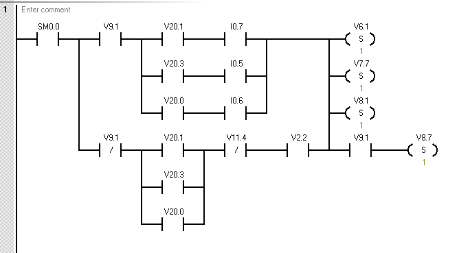
Within the scope of an electrical diagram, this symbol. Ladder diagram systems are the best programming language to learn and the smart thing that the designers did was make it very similar to standard since we started this plc tutorial with how a plc works and what it is then continued to what ladder logic symbols are then talked about timers and. These diagrams documented how connections between devices were made on relay panels; Each device in the relay rack would be represented by a symbol on the ladder diagram with connections between those devices shown. —( )— a regular coil, energized whenever its rung is closed. The vertical lines on the left and right are called the power rails. Ladder diagram is a conventional form of programming the programmable logic controllers (plcs). Ladder logic was originally a written method to document the design and construction of relay racks as used in manufacturing and process control. An example plc ladder logic diagram appears in figure 2.9. Otherwise, the ladder diagram is nothing more than black symbols on a white background. Draw ladder diagrams for simple logic operations. Now let's talk about the six most used logic. Introduction to plc ladder diagrams.
Vertical power rails and horizontal control rungs. symbols also differ a bit from common electronics notation: 4.2 ladder logic symbols the set of symbols which are commonly used in lad are as follows Learn about ladder logic symbols, diagrams & more. The ladder diagram is the universal programming language of plc. Ladder logic tutorial with ladder logic symbols diagrams ladder logic programming examples ladder logic world.
Plc Ladder Logic Symbols Microdigisoft from microdigisoft.com An example plc ladder logic diagram appears in figure 2.9. Ladder diagram is a conventional form of programming the programmable logic controllers (plcs). Ld having good representation for discrete logic. N the symbols are ladder logic instructions n the plc scans (executes) the symbols ladder logic diagram. Plc ladder logic consists of a commonly used set of symbols that represent instructions. This diagram is developed from structured relay contacts that describe the flow of electric current. Vertical power rails and horizontal control rungs. symbols also differ a bit from common electronics notation: Imagine drawing an electrical circuit on your if you are familiar with electrical schematics you will notice the relay and coil symbols.
Early relay diagram symbols were literal.
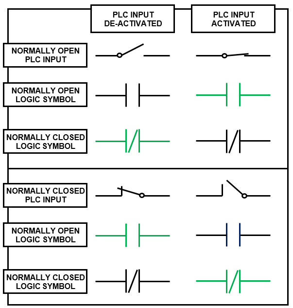
Relay logic's ladder diagrams used physical contacts, coils, switches, and lots of other devices for every single function on a machine. Each symbols represents instruction which you need while building ladder logic. Ladder diagram systems are the best programming language to learn and the smart thing that the designers did was make it very similar to standard since we started this plc tutorial with how a plc works and what it is then continued to what ladder logic symbols are then talked about timers and. Ladder diagrams describe programs in graphical form, used in plc programming. Plc learning series 4 : The rung above incorporates the normally open and normally closed ladder logic symbols. Now let's talk about the six most used logic. And gate plc ladder logic diagram: All the ladder logic symbols or plc programming instruction available in the format of bit logic , arithmetic, logical. Ladder logic symbols pdfall software. Electricity is shown going through the left side of the ladder in order to energize the input and achieve the output. The structure behind ladder logic is based on the electrical ladder diagrams that were used with relay logic. Relay coils are drawn as circles, with relay.
Primary programming language for plcs. Relay logic's ladder diagrams used physical contacts, coils, switches, and lots of other devices for every single function on a machine. Ld having good representation for discrete logic. Control elements are entered in the ladder diagram by positioning the cursor and selecting the element from a list. Ladder logic symbols are the basic building blocks for ladder diagrams.
Electromechanical Relay Logic Worksheet Digital Circuits from sub.allaboutcircuits.com Ladder diagrams differ from regular schematic diagrams of the sort common to electronics technicians primarily in the strict orientation of the wiring: Each symbol represents a certain ladder instruction. • continuous motor operation with a momentary start switch is possible if a. In ladder logic, these symbols are also known as bit logic instructions. How a ladder logic diagram works? Draw ladder diagrams for simple logic operations. Control elements are entered in the ladder diagram by positioning the cursor and selecting the element from a list. Ladder diagram electrical symbols chart.
In the following example shown on picture 2 the cursor has been placed in the position to the right.
Now let's talk about the six most used logic. Plc ladder logic consists of a commonly used set of symbols that represent instructions. Within the scope of an electrical diagram, this symbol. Electricity is shown going through the left side of the ladder in order to energize the input and achieve the output. These diagrams documented how connections between devices were made on relay panels; However, a coil can also be used with internal memory in order to trigger internal logic instructions. And gate plc ladder logic diagram: When both the inputs are high the output y0 is high. Ladder logic tutorial with ladder logic symbols diagrams ladder logic programming examples ladder logic world. Ladder diagrams differ from regular schematic diagrams of the sort common to electronics technicians primarily in the strict orientation of the wiring: There are many control situations requiring actions to be initiated when a certain combination of conditions is realized. An example plc ladder logic diagram appears in figure 2.9. Easy to learn and read the program.