Home
› Wiring A Trailer With Brakes - Installing Electric Brakes On Your Trailer R And P Carriages Cargo Utility Dump Equipment Car Haulers And Enclosed Trailers In Chicago Ottawa Dekalb And Joliet Il - Get it as soon as tue, may 25.
Wiring A Trailer With Brakes - Installing Electric Brakes On Your Trailer R And P Carriages Cargo Utility Dump Equipment Car Haulers And Enclosed Trailers In Chicago Ottawa Dekalb And Joliet Il - Get it as soon as tue, may 25.
Wiring A Trailer With Brakes - Installing Electric Brakes On Your Trailer R And P Carriages Cargo Utility Dump Equipment Car Haulers And Enclosed Trailers In Chicago Ottawa Dekalb And Joliet Il - Get it as soon as tue, may 25.. This is done by cutting the wire about half an inch back and attaching it to the shrink hose of the trailer. The four wires control the turn signals, brake lights and taillights or running lights. If this is correct, you will need to connect one of the wires to the brake controller output wire on your trailer connector and the other wire will need to be grounded to a clean metal surface on the trailer. 7 way plug wiring diagram standard wiring* post purpose wire color tm park light green (+) battery feed black rt right turn/brake light brown lt left turn/brake light red s trailer electric brakes blue gd ground white a accessory yellow this is the most common (standard) wiring scheme for rv plugs and the one used by major auto manufacturers today. 4.2 out of 5 stars 52.
The extra wire, as a rule, is used to power backup lights. Each of your new brakes will have two wires for the brake magnet. 4.2 out of 5 stars 52. Photo by adam wright 2010. How electric trailer brakes work.
Wiring Trailer Lights With A 7 Way Plug It S Easier Than You Think Etrailer Com from www.etrailer.com The four wires control the turn signals, brake lights and taillights or running lights. How electric trailer brakes work. It ought not be carrying significant loads through the trip. Trailer wiring diagrams trailer wiring connectors various connectors are available from four to seven pins that allow for the transfer of power for the lighting as well as auxiliary functions such as an electric trailer brake controller, backup lights, or a 12v power supply for a winch or interior trailer lights. Let trailer kit snowmobile light kit submersible led trailer wiring kit brake stop turn tail trailer light bar for camper truck rv boat snowmobile under 80 inch led trailer kit. This guide will be discussing wiring diagram for tandem axle trailer with brakes.what are the benefits of understanding these understanding? This car is designed not only to travel one place to another but also to take heavy loads. 7 way plug wiring diagram standard wiring* post purpose wire color tm park light green (+) battery feed black rt right turn/brake light brown lt left turn/brake light red s trailer electric brakes blue gd ground white a accessory yellow this is the most common (standard) wiring scheme for rv plugs and the one used by major auto manufacturers today.
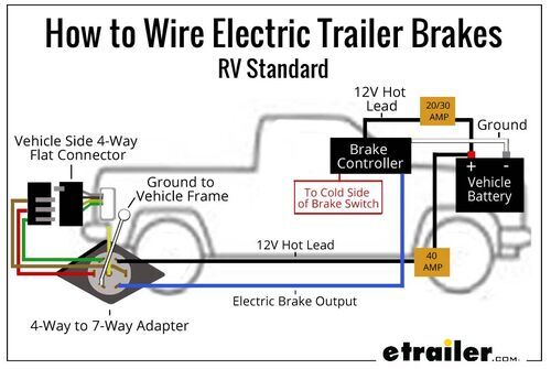
There is a very basic wiring electric trailer brakes diagram.
If a trailer has brakes, then it needs a connector with at least 5 pins. This is accomplished by tapping into the tow vehicle's electrical harness to transfer power to the trailer wiring system. This car is designed not only to travel one place to another but also to take heavy loads. You can find a decent circuit tester on amazon.com for around $20, or just shop around for what you want. A wiring diagram is a kind of schematic which uses abstract pictorial symbols showing every one of the interconnections of components in a very system. It does not matter which wire is used for power or ground because they are not polarized. This guide will be discussing wiring diagram for tandem axle trailer with brakes.what are the benefits of understanding these understanding? Assortment of electric trailer brake wiring schematic. From lights to brakes, there are a lot of parts on a trailer that need electricity to work. Usually 12 gauge wire is recommended for the brake circuit, and connecting your brake assemblies. Trailer wiring diagrams trailer wiring connectors various connectors are available from four to seven pins that allow for the transfer of power for the lighting as well as auxiliary functions such as an electric trailer brake controller, backup lights, or a 12v power supply for a winch or interior trailer lights. I go over all the basics on wiring up your vehicle trailer harness and electric brakes. Get it as soon as tue, may 25.
By law, trailer lighting must be connected into the tow vehicle's wiring system to provide trailer running lights, turn signals and brake lights. It also talks about electric brake controller.thanks for watching ! This is done by cutting the wire about half an inch back and attaching it to the shrink hose of the trailer. As the name implies, they use four wires to carry out the vital lighting functions. A wiring diagram is a streamlined conventional pictorial representation of an electric circuit.
The Trailer Breakaway Kit And How To Use It Mechanical Elements from mechanicalelements.com I go over all the basics on wiring up your vehicle trailer harness and electric brakes. If a trailer has brakes, then it needs a connector with at least 5 pins. The extra wire, as a rule, is used to power backup lights. It ought not be carrying significant loads through the trip. How electric trailer brakes work. By law, trailer lighting must be connected into the tow vehicle's wiring system to provide trailer running lights, turn signals and brake lights. Everything you need for towing vehicle wiring I have included a diagram for you.
Photo by adam wright 2010.
However if you have a long trailer with multiple axles and brake assemblies, then 10 gauge wire is recommended. Get it as soon as tue, may 25. Browse our selection of trailer hitch wiring harnesses for the one that meets your towing needs. Fenders, couplers, lights & more. They also provide a wire for a ground connection. 7 way plug wiring diagram standard wiring* post purpose wire color tm park light green (+) battery feed black rt right turn/brake light brown lt left turn/brake light red s trailer electric brakes blue gd ground white a accessory yellow this is the most common (standard) wiring scheme for rv plugs and the one used by major auto manufacturers today. It does not matter which wire is used for power or ground because they are not polarized. Caution inadequate grounding may cause intermittent braking or lack of sufficient voltage to trailer brakes. If a trailer has brakes, then it needs a connector with at least 5 pins. I have included a diagram for you. This guide will be discussing wiring diagram for tandem axle trailer with brakes.what are the benefits of understanding these understanding? There is a very basic wiring electric trailer brakes diagram. The white wire must be connected to a suitable ground location.
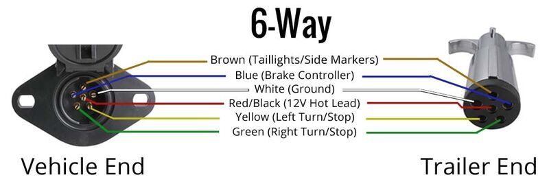
As the name implies, they use four wires to carry out the vital lighting functions. Trailer wiring diagram 6 pin (round) One wire is for 12 volt power to the brake magnets and the other wire should be grounded either to the trailer frame or to the main trailer ground wire. The negative terminal of the battery is a suitable ground location in the. Caution inadequate grounding may cause intermittent braking or lack of sufficient voltage to trailer brakes.
Wiring Trailer Lights With A 6 Way Plug It S Easier Than You Think Etrailer Com from www.etrailer.com Using a trailer is quickly becoming part of the american lifestyle. The suggested minimum for the ground, brake power, and battery hot lead wires is 12 gauge. The extra wire, as a rule, is used to power backup lights. They also provide a wire for a ground connection. 4.2 out of 5 stars 52. Let trailer kit snowmobile light kit submersible led trailer wiring kit brake stop turn tail trailer light bar for camper truck rv boat snowmobile under 80 inch led trailer kit. A wiring diagram is a kind of schematic which uses abstract pictorial symbols showing every one of the interconnections of components in a very system. 7 way plug wiring diagram standard wiring* post purpose wire color tm park light green (+) battery feed black rt right turn/brake light brown lt left turn/brake light red s trailer electric brakes blue gd ground white a accessory yellow this is the most common (standard) wiring scheme for rv plugs and the one used by major auto manufacturers today.
Blue wire (brake output to trailer) 1.
By law, trailer lighting must be connected into the tow vehicle's wiring system to provide trailer running lights, turn signals and brake lights. As the name implies, they use four wires to carry out the vital lighting functions. From lights to brakes, there are a lot of parts on a trailer that need electricity to work. Brake switch (red) this is usually found near the top of the brake pedal. Blue wire (brake output to trailer) 1. This guide will be discussing wiring diagram for tandem axle trailer with brakes.what are the benefits of understanding these understanding? Photo by adam wright 2010. A wiring diagram is a kind of schematic which uses abstract pictorial symbols showing every one of the interconnections of components in a very system. The 5th pin, a blue wire, gives power to operate (or disable) the trailer brakes. It ought not be carrying significant loads through the trip. There is a very basic wiring electric trailer brakes diagram. 5% coupon applied at checkout save 5% with coupon. This car is designed not only to travel one place to another but also to take heavy loads.