Home
› Lcd Wiring Diagram Arduino / Arduino LCD Wiring Diagram | The DIY Life / In order to control the lcd and display characters, you will need to add a few extra connections.
Lcd Wiring Diagram Arduino / Arduino LCD Wiring Diagram | The DIY Life / In order to control the lcd and display characters, you will need to add a few extra connections.
Lcd Wiring Diagram Arduino / Arduino LCD Wiring Diagram | The DIY Life / In order to control the lcd and display characters, you will need to add a few extra connections.. In order to control the lcd and display characters, you will need to add a few extra connections. Pillow tft lcd color monitor wiring diagram. Arduino and 1602a lcd wiring diagram. These all displays can be interfaced using this tutorial. Before wiring the lcd screen to your arduino board we suggest to solder a pin header strip to the 14 (or 16) pin count connector of the lcd screen.
I'll explain that and show you a demonstration sketch that. Pillow tft lcd color monitor wiring diagram. These all displays can be interfaced using this tutorial. Arduino water level sensor tutorial the geek pub. The resistor in the diagram above sets the backlight brightness.
Interfacing 16×2 LCD with Arduino - Technology & Hacking from i2.wp.com If you happen to be better reading that looking at diagrams, let's go over the pinouts in detail. The neat thing about this device is how the pushbuttons are wired. Then these lcd displays might be the perfect fit. In order to control the lcd and display characters, you will need to add a few extra connections. Arduino hmi tft lcd module electrical load controller. Check the wiring diagram below and the pinout table from the /* example sketch to create and display custom characters on character lcd with arduino and liquidcrystal library. These displays can be wired in either 4 bit mode or 8 bit mode. Getting the arduino lcd display wiring project together relies on just a few simple parts.
This tutorial includes datasheet, working, pinout, wiring/schematic, code & custom character generation.
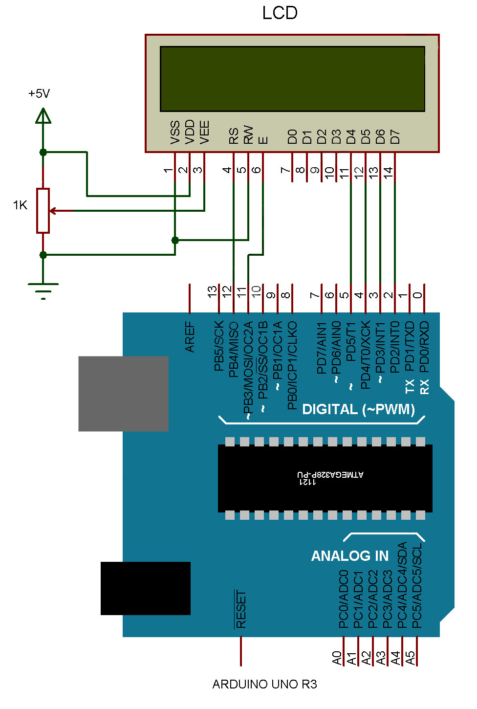
Read cabling diagrams from negative to positive plus redraw the signal as a straight always adhere to manufacturer's wiring diagrams when replacing the fixture, and understand—and use—your home's grounding system to make sure. Lcd displays available in various sizes 8×1, 16×1, 16×2, 16×4, 20 char x 4 lines. Before wiring up your lcd to the arduino, make sure that your lcd has the same pin numbering as the one in the circuit diagram below. Before wiring the lcd screen to your arduino or genuino board we suggest to solder a pin header strip to the 14 or 16 pin count connector of the lcd screen as you can see in the image above. Interface an lcd screen with an arduino to provide a display for your project. Arduino and 1602a lcd wiring diagram. Wiring the lcd in 4 bit mode is usually preferred since it uses four less wires than 8 bit follow the diagram below to wire the lcd to your arduino: Then these lcd displays might be the perfect fit. Displays text sent from the arduino serial monitor window on the top line of the lcd. I'll explain that and show you a demonstration sketch that. Getting the arduino lcd display wiring project together relies on just a few simple parts. In order to control the lcd and display characters, you will need to add a few extra connections. The resistor in the diagram above sets the backlight brightness.
Pillow tft lcd color monitor wiring diagram. Arduino water level sensor tutorial the geek pub. Before wiring the lcd screen to your arduino board we suggest to solder a pin header strip to the 14 (or 16) pin count connector of the lcd screen. Then these lcd displays might be the perfect fit. Arduino lcd wiring diagram source:
Arduino Keypad Wiring Diagram - Wiring Diagram Schema from b3van8qm1o7ou9d3b48qdhsg-wpengine.netdna-ssl.com Before wiring the lcd screen to your arduino or genuino board we suggest to solder a pin header strip to the 14 or 16 pin count connector of the lcd screen as you can see in the image above. Getting the arduino lcd display wiring project together relies on just a few simple parts. Want your arduino projects to display status messages or sensor readings? You'll of course need an arduino and the lcd display. These displays can be wired in either 4 bit mode or 8 bit mode. How to interfacing i2c lcd using arduino looking at the circuit diagram you can see that pin numbers 15 and 16 are sda and scl of pc8574p ic so you need to connect. Learn to use lcd displays with an arduino. The neat thing about this device is how the pushbuttons are wired.
After loading this program, open the serial monitor window and send some.
Want your arduino projects to display status messages or sensor readings? Spare time notebook building an arduino lcd interface part i. Arduino powered glcd graphic lcd. These displays can be wired in either 4 bit mode or 8 bit mode. How to interfacing i2c lcd using arduino looking at the circuit diagram you can see that pin numbers 15 and 16 are sda and scl of pc8574p ic so you need to connect. Wiring the lcd in 4 bit mode is usually preferred since it uses four less wires than 8 bit follow the diagram below to wire the lcd to your arduino: Getting the arduino lcd display wiring project together relies on just a few simple parts. Arduino water level sensor tutorial the geek pub. In order to control the lcd and display characters, you will need to add a few extra connections. Then these lcd displays might be the perfect fit. Learn interfacing 16x2 lcd module with arduino uno. Arduino lcd wiring arduino lcd set up and programming guide. Before wiring up your lcd to the arduino, make sure that your lcd has the same pin numbering as the one in the circuit diagram below.
Spare time notebook building an arduino lcd interface part i. How to interfacing i2c lcd using arduino looking at the circuit diagram you can see that pin numbers 15 and 16 are sda and scl of pc8574p ic so you need to connect. All types of lcds, including i2c and display shields are covered here.article with learn to use lcd displays with an arduino. Tft lcd monitor reversing camera wiring diagram. Arduino lcd wiring diagram source:
Interfacing LCD with Arduino (Arduino Series - Part 04) from www.elprocus.com Before wiring up your lcd to the arduino, make sure that your lcd has the same pin numbering as the one in the circuit diagram below. For this, do the connections as shown in the diagram above. I'll explain that and show you a demonstration sketch that. Check the wiring diagram below and the pinout table from the /* example sketch to create and display custom characters on character lcd with arduino and liquidcrystal library. If you happen to be better reading that looking at diagrams, let's go over the pinouts in detail. After loading this program, open the serial monitor window and send some. Arduino lcd wiring diagram this allows for riders to be more visible during the night or even on cloudy days an arduino mega is used to control the touchscreen while a pic 16f88 is used for the other components on the helmet imagine spinning a globe to select a place of interest and then hearing a. By facybulkaposted on july 20, 20167 views.
Learn interfacing 16x2 lcd module with arduino uno.
Wiring the lcd in 4 bit mode is usually preferred since it uses four less wires than 8 bit follow the diagram below to wire the lcd to your arduino: Pillow tft lcd color monitor wiring diagram. Read cabling diagrams from negative to positive plus redraw the signal as a straight always adhere to manufacturer's wiring diagrams when replacing the fixture, and understand—and use—your home's grounding system to make sure. 16×2 lcd with arduino wiring diagram. Arduino lcd wiring diagram source: Before wiring up your lcd to the arduino, make sure that your lcd has the same pin numbering as the one in the circuit diagram below. Lcds like these are very popular and broadly used in electronics projects as they are good for displaying information like sensors data from your project, and also they are very cheap. Lcd wiring diagram arduino have some pictures that related each other. Arduino hmi tft lcd module electrical load controller. Before wiring the lcd screen to your arduino uno or genuino board we suggest to solder a pin header strip to the 14 (or 16) pin count connector of the lcd screen. For this, do the connections as shown in the diagram above. In order to control the lcd and display characters, you will need to add a few extra connections. In 16x2 lcd there are 16 pins over all if there is a back light, if there is no back light there will be 14 pins.