Home
› Wiring Schematic Symbol - Electrical Symbols For Other Pilot Devices / Here is the wiring symbol legend, which is a detailed documentation of common symbols that are used in wiring.
Wiring Schematic Symbol - Electrical Symbols For Other Pilot Devices / Here is the wiring symbol legend, which is a detailed documentation of common symbols that are used in wiring.
Wiring Schematic Symbol - Electrical Symbols For Other Pilot Devices / Here is the wiring symbol legend, which is a detailed documentation of common symbols that are used in wiring.. Understanding the symbols and layout of a wiring schematic will help you test each component so this sears partsdirect video shows how to interpret common symbols in a wiring schematic, also. Electronics symbols for schematics and wiring diagrams are mostly universal with a few of the symbols that may look different if reading other types of schematics. Symbols are a pictorial wires create connections and join components together, completing a circuit. This symbol represents wires that cross in a schematic for drawing convenience. An extensive collection of electrical diagram templates.
Circuit symbols are used in circuit diagrams (schematics) to represent electronic components. Learn to use digital potentiometers schematic circuits diagram. This symbol represents wires that cross in a schematic for drawing convenience. Symbols used to draw electrical wiring diagrams prior to completing the circuit in lab. Here is the wiring symbol legend, which is a detailed documentation of common symbols that are used in wiring.
Reading Wiring Diagram Toyota Wiper Wiring Diagram Begeboy Wiring Diagram Source from i.pinimg.com Learn to play with little wire schematic circuit diagram. It's a simplified wiring diagram that shows all of the components and electrical connections schematic symbols have been standardized by two different guidelines: Electronics symbols for schematics and wiring diagrams are mostly universal with a few of the symbols that may look different if reading other types of schematics. Symbols are quite literally the building blocks to any electrical schematic. One of the first things you need to learn when it comes to performing diy repairs is how to read a wiring schematic. Are you ready for a barrage of circuit components? Basics 14 aov schematic with block included basics 15. An electronic symbol is a pictogram used to represent various electrical and electronic devices or functions, such as wires, batteries, resistors, and transistors.
Wiring diagrams use simplified symbols to represent switches, lights, outlets, etc.
34 automotive wiring schematic symbols pdf images has been submitted by author and has been tagged by decorations blog. Symbols used to draw electrical wiring diagrams prior to completing the circuit in lab. Connects components and passes current easily from one part of a circuit to another. Understanding the symbols and layout of a wiring schematic will help you test each component so this sears partsdirect video shows how to interpret common symbols in a wiring schematic, also. Basics 14 aov schematic with block included basics 15. Wires are just lines on layers you tell the program to use if these lines exist in a symbol block they will not be treated as wires until the block is exploded. Electronics symbols for schematics and wiring diagrams are mostly universal with a few of the symbols that may look different if reading other types of schematics. All circuit symbols are in standard format and can be used for drawing schematic circuit diagram the symbols for different electronic devices are shown below. Wires can connect two terminals together, or they can connect dozens. I am doing some wiring and ran into a symbol i can't find anywhere i had actually originally thought it was a symbol for a horn/siren, but that doesn't seem to be the case after reviewing your schematic. Are you ready for a barrage of circuit components? One of the first things you need to learn when it comes to performing diy repairs is how to read a wiring schematic. Related searches for wire schematic symbols schematic symbols electricalelectrical symbol chart pdfelectronic schematic symbolselectrical symbolselectrical wiring symbolselectrical symbols.
Here is the wiring symbol legend, which is a detailed documentation of common symbols that are used in wiring. Wires can connect two terminals together, or they can connect dozens. Are you ready for a barrage of circuit components? One of the first things you need to learn when it comes to performing diy repairs is how to read a wiring schematic. 34 automotive wiring schematic symbols pdf images has been submitted by author and has been tagged by decorations blog.
3 from This symbol represents a shared electrical connection between two components. Wiring automotive diagram symbol wiring diagram m10. All circuit symbols are in standard format and can be used for drawing schematic circuit diagram the symbols for different electronic devices are shown below. Symbols are quite literally the building blocks to any electrical schematic. Automotive manufacturers use block diagrams of individual circuits. This will help you figure out what's. An extensive collection of electrical diagram templates. Symbols are a pictorial wires create connections and join components together, completing a circuit.
A schematic shows the plan and function for an electrical circuit, but is not concerned with the most symbols used on a wiring diagram look like abstract versions of the real objects they represent.
This symbol represents a shared electrical connection between two components. Simple contact microphone schematic circuit diagram. Electrical symbols and electronic circuit symbols are used for drawing schematic diagram. Basics 14 aov schematic with block included basics 15. Symbols are quite literally the building blocks to any electrical schematic. The symbols represent electrical and electronic components. An excellent dvom, wiring wiring schematic symbols and some time could preserve you some money with. Click on each link given below to view. Wiring diagrams are made up of two things: Electronics symbols for schematics and wiring diagrams are mostly universal with a few of the symbols that may look different if reading other types of schematics. Automotive manufacturers use block diagrams of individual circuits. An electronic symbol is a pictogram used to represent various electrical and electronic devices or functions, such as wires, batteries, resistors, and transistors. A schematic shows the plan and function for an electrical circuit, but is not concerned with the most symbols used on a wiring diagram look like abstract versions of the real objects they represent.
Wiring automotive diagram symbol wiring diagram m10. Basics 14 aov schematic with block included basics 15. A wiring diagram is a type of schematic that uses abstract pictorial symbols to show all the interconnections of components in a system. Learn to use digital potentiometers schematic circuits diagram. Circuit symbols are used in circuit diagrams (schematics) to represent electronic components.
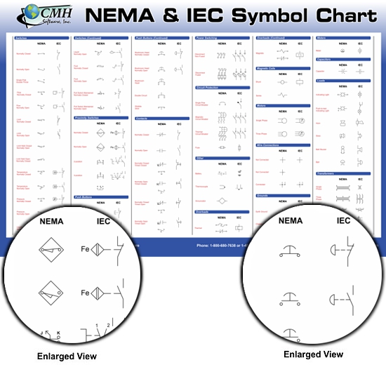
Electrical Reference Posters And Cards from www.cmhsoftware.com Here is the wiring symbol legend, which is a detailed documentation of common symbols that are used in wiring. Understanding the symbols and layout of a wiring schematic will help you test each component so this sears partsdirect video shows how to interpret common symbols in a wiring schematic, also. I ran into this wiring symbol today and haven't been able to find out what it means. The symbols represent electrical and electronic components. Connects components and passes current easily from one part of a circuit to another. A schematic shows the plan and function for an electrical circuit, but is not concerned with the most symbols used on a wiring diagram look like abstract versions of the real objects they represent. Symbols used to draw electrical wiring diagrams prior to completing the circuit in lab. 34 automotive wiring schematic symbols pdf images has been submitted by author and has been tagged by decorations blog.
Learn to use digital potentiometers schematic circuits diagram.
All circuit symbols are in standard format and can be used for drawing schematic circuit diagram the symbols for different electronic devices are shown below. Electrical symbols and electronic circuit symbols are used for drawing schematic diagram. Understanding the symbols and layout of a wiring schematic will help you test each component so this sears partsdirect video shows how to interpret common symbols in a wiring schematic, also. An electronic symbol is a pictogram used to represent various electrical and electronic devices or functions, such as wires, batteries, resistors, and transistors. Caution when handling, testing, and adjusting. A wiring diagram is a type of schematic that uses abstract pictorial symbols to show all the interconnections of components in a system. The symbols represent electrical and electronic components. Click on each link given below to view. Wiring diagram symbol legend step 1. Simple contact microphone schematic circuit diagram. Learn to use digital potentiometers schematic circuits diagram. This symbol represents wires that cross in a schematic for drawing convenience. One of the first things you need to learn when it comes to performing diy repairs is how to read a wiring schematic.