Rj45 Connector Diagram : Crossover Cable Make Ethernet Rj45 - Wiring Diagram Schemas : Ethernet cable utp rj45 wiring diagram.. Two standards define how the rj45 pinouts to arrange the individual eight wires when linking rj45 connector to a cable. Pinout diagrams and wire colours for cat 5e, cat 6 and cat 7. There are multiple pinouts for rj45 connectors including straight through (t568a or t568b). How to crimp ethernet rj45. Rj45 pinout diagram shows the way how that connector provides communication with network devices.
Rj45 (registered jack 45) is the connector that consists of 8 metal connection point. Rj45 pinout diagram shows wiring for standard t568b, t568a and crossover cable! Rj45 pinout diagram shows the way how that connector provides communication with network devices. How to wire cable ethernet cat 5 5e ,6 wiring diagram rj45 plug jackwiring a network cableethernet patch cable how to install a ethernet cable homerj45. An easy way to remember the two different rj45 connector pinouts is t568a is used in america and asia, and the t568b is used in britain(uk) and.
Wiring Diagram Rj45 To Db9 | Wiring Library from www.sealevel.com Rj45 wiring pinout for crossover and straight through lan ethernet network cables. Rj45 pinout diagram shows wiring for standard t568b, t568a and crossover cable! A pinout is a specific arrangement of wires that dictate how the connector is terminated. Assortment of rj45 connector wiring diagram. A wiring diagram is a streamlined conventional pictorial depiction of an electric circuit. Nowdays ethernet is a most common networking standard for lan (local area network) communication. Ethernet cable utp rj45 wiring diagram. There are multiple pinouts for rj45 connectors including straight through (t568a or t568b).
Rj45 wiring pinout for crossover and straight through lan ethernet network cables.
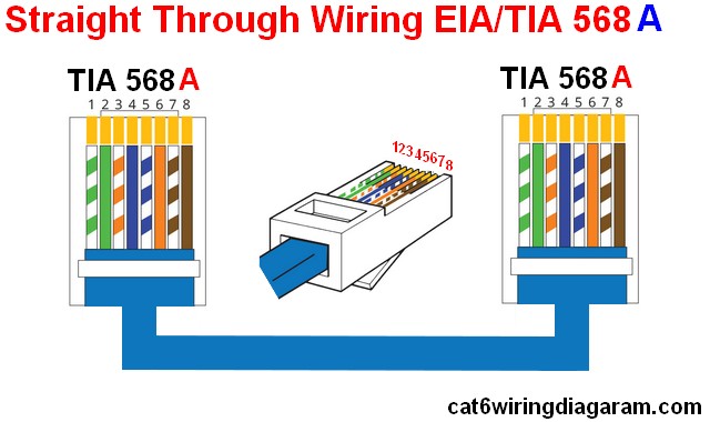
How to wire cable ethernet cat 5 5e ,6 wiring diagram rj45 plug jackwiring a network cableethernet patch cable how to install a ethernet cable homerj45. They are eia/tia 568a and eia/tia 568b. Rj45 pinout diagram shows wiring for standard t568b, t568a and crossover cable! Two standards define how the rj45 pinouts to arrange the individual eight wires when linking rj45 connector to a cable. There are multiple pinouts for rj45 connectors including straight through (t568a or t568b). Ethernet cable utp rj45 wiring diagram. Nowdays ethernet is a most common networking standard for lan (local area network) communication. There are mainly two types of ethernet cable pin outs. Push the wires firmly into the plug. It reveals the parts of the circuit as simplified forms, as well as the power and also signal connections between the tools. As compared to the rj11 connector, rj45 comes with more applications including ethernet networking, industrial automation, and telecommunications. Pinout diagrams and wire colours for cat 5e, cat 6 and cat 7. Rj45 wiring pinout for crossover and straight through lan ethernet network cables.
Assortment of rj45 connector wiring diagram. How to crimp ethernet rj45. There are multiple pinouts for rj45 connectors including straight through (t568a or t568b). Push the wires firmly into the plug. As we all know, there are two wiring schemes:
Rj45 Ethernet Wiring Diagram Cat 6 Color Code - Cat 5 Cat 6 Wiring Diagram - Color Code from 4.bp.blogspot.com Rj45 pinout diagram shows wiring for standard t568b, t568a and crossover cable! As we all know, there are two wiring schemes: There are two standards that are used for rj45 connector wiring. The ethernet cable used to wire a rj45 connector of network interface card to a hub, switch or network outlet. It reveals the parts of the circuit as simplified forms, as well as the power and also signal connections between the tools. There are mainly two types of ethernet cable pin outs. How to wire cable ethernet cat 5 5e ,6 wiring diagram rj45 plug jackwiring a network cableethernet patch cable how to install a ethernet cable homerj45. Two standards define how the rj45 pinouts to arrange the individual eight wires when linking rj45 connector to a cable.
The ethernet cable used to wire a rj45 connector of network interface card to a hub, switch or network outlet.
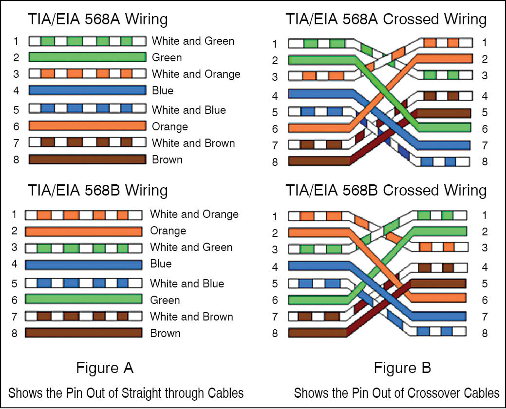
There are two standards that are used for rj45 connector wiring. As compared to the rj11 connector, rj45 comes with more applications including ethernet networking, industrial automation, and telecommunications. A wiring diagram is a streamlined conventional pictorial depiction of an electric circuit. Inspect each wire is flat even at the front of the plug. Pinout diagrams and wire colours for cat 5e, cat 6 and cat 7. Nowdays ethernet is a most common networking standard for lan (local area network) communication. As we all know, there are two wiring schemes: An easy way to remember the two different rj45 connector pinouts is t568a is used in america and asia, and the t568b is used in britain(uk) and. Assortment of rj45 connector wiring diagram. There are mainly two types of ethernet cable pin outs. Rj45 (registered jack 45) is the connector that consists of 8 metal connection point. Rj45 pinout diagram shows the way how that connector provides communication with network devices. They are eia/tia 568a and eia/tia 568b.
There are multiple pinouts for rj45 connectors including straight through (t568a or t568b). Rj45 connectors are connected on both sides of the cables that act as a source of data transmission. They are eia/tia 568a and eia/tia 568b. Rj45 pinout diagram shows wiring for standard t568b, t568a and crossover cable! A pinout is a specific arrangement of wires that dictate how the connector is terminated.
RJ45 Cable Tester | Detailed Circuit Diagram Available from electronicsforu.com Rj45 pinout diagram shows the way how that connector provides communication with network devices. Rj45 (registered jack 45) is the connector that consists of 8 metal connection point. As we all know, there are two wiring schemes: A rj45 connector is a modular 8 position, 8 pin connector used for terminating cat5e or cat6 twisted pair cable. Pinout diagrams and wire colours for cat 5e, cat 6 and cat 7. The ethernet cable used to wire a rj45 connector of network interface card to a hub, switch or network outlet. There are mainly two types of ethernet cable pin outs. An easy way to remember the two different rj45 connector pinouts is t568a is used in america and asia, and the t568b is used in britain(uk) and.
Ethernet cable utp rj45 wiring diagram.
Rj45 wiring pinout for crossover and straight through lan ethernet network cables. There are mainly two types of ethernet cable pin outs. A pinout is a specific arrangement of wires that dictate how the connector is terminated. Nowdays ethernet is a most common networking standard for lan (local area network) communication. Assortment of rj45 connector wiring diagram. They are eia/tia 568a and eia/tia 568b. Rj45 connectors are connected on both sides of the cables that act as a source of data transmission. Rj45 pinout diagram shows wiring for standard t568b, t568a and crossover cable! Two standards define how the rj45 pinouts to arrange the individual eight wires when linking rj45 connector to a cable. Rj45 pinout diagram shows the way how that connector provides communication with network devices. As we all know, there are two wiring schemes: Rj45 (registered jack 45) is the connector that consists of 8 metal connection point. It reveals the parts of the circuit as simplified forms, as well as the power and also signal connections between the tools.